You need a programmer which can f.i. be a Raspberry Pi, an FT2232H or a ch341a. Then you need to connect your programmer to the BIOS chip. For some desktop mainboards the BIOS chip is socketed so that you can move it out with a tweezer or pincer. Moving it out by hand can be a bit risky as you do not want to bend its pins. If there is no capacitor in the way you may prefer using a pincer since it has a better grip than the tweezer. With a tweezer first remove any PCIe cards which may be in your way, then get a good grip and try to move the BIOS chip slowly and evtl. by lightly swaying out. You may get tweezers at a drugstore. Make sure that the mainboard is powered off when you try to remove the BIOS chip. This could result in a broken or malfunctioning board otherwise. Once you have moved it out you can place the BIOS chip on a breadboard. You will connect your programmer to the breadboard with female-male and male-male jumper wires. See before how a breadboard is wired. The pluggable BIOS chip and the socket both use to have a notch so that you can not insert the BIOS chip in the wrong direction.
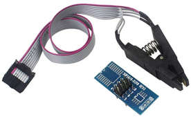
socketed BIOS chip For notebooks and many desktops the BIOS chip is usually soldered on the mainboard. You connect your programmer to a SPI clip which you will then clip on the BIOS chip. This method is called ISP - In System Programming. The safer way is to power the BIOS chip with the programmer during flashing. However if the voltage falls down when you connect the clip to the mainboard you may need to power the whole mainboard with your PSU - Power Supply Unit. This is because the other parts of the mainboard may suck power. The procedure is a bit risky. In this case you will keep GND (Ground, - Voltage) connected but unconnect VCC (+ Voltage) because the power comes from the board. You may want to unconnect the accumulator/
Now you need to establish the wiring. Get the datasheet of your BIOS chip. You may find that by looking on what is printed on the BIOS chip. You may need a magnifier or a digital camera though in order to decipher what is written on a certain module. If your mainboard supports flashrom flashrom -V may also print the name of the BIOS chip. Then get a description of your programmer. Note that the programmer may have a different/extended name than the chip used on the programmer. Finally the PIN names between your BIOS chip and the programmer description will likely not match exactly. Here we have a table that matches a few names:
| name on the chip | name on the programmer |
|---|---|
| DIO or DI (Data Input) | MOSI (Mater Out Slave In) |
| DO (Data Output) | MISO (Mater In Slave Out) |
| CLK (Clock) | SCK (Serial Clock) |
| CS (Chip Select) / CE (Chip Enable) | CS0 (Chip Select Zero) |
| VSS | GND (ground voltage) |
| NC (Not Connected) | – |
WP (Write Protect) and HOLD need to be connected to VCC for external flashing (Hi). On a mainboard these pins are already preconnected. Take care if your chip has Quad mode. Then WP & HOLD can be reconfigured as additional data input and output when Quad Enable = 1. If your chip has a quad mode and is currently configured to use it then you need to connect WP and HOLD with a resistor of more than 1kΩ (I have used 10kΩ) to VCC instead of connecting it directly.
With a Raspberry Pi go to the settings GUI menu select enable the SPI device and then reboot. After that /dev/spidev0.0 appears. For USB programmers see with lsusb whether they show up. If the programmer is not recognized as USB device you need to power it correctly by setting the correct jumpers or by wiring respective pins to the 5V power supply provided with the USB pins.
Finally do not fully rely on this description if you wanna flash the BIOS/UEFI of a new mainboard. Seek for help at #flashrom at irc.freenode.net (IRC ~ Internet Relay Chat). Connecting your wires wrongly or trying to flash with 5V instead of 3.3V may damage your mainboard. If you want to get better support or if you wanna program your own coreboot firmware/BIOS for your machine you may want to ask the manufacturer of your computer for the schematic of your board. Coreboot is a free and open source BIOS/UEFI. It is smaller, more secure and boots faster than the proprietary UEFI.
If things do not want to work use 10cm jumper wires instead of 15cm or 20cm jumper wires or test it with a BIOS chip not connected to a mainboard. You may purchase one at an electronic shop like mouser.com; any *25* SPI NOR flash with the settings as for the darp5 should work. I have an AT25SF128A-SHB-T with QE=0 default and an AT25QF128A-SHB-T with QE=1 default. Shortening the cable of your clip may also help. As final resort you could also solder in order to circumvent the SPI clip.
In general you only need to flash externally when there is either no integrated flashrom support, your machine does not boot due to a BIOS failure or when your BIOS is tampered maliciously the malware intercepting the software communication between flashrom and the BIOS chip so that flashing a known good BIOS seems to succeed but in deed does not change the BIOS. The latter should only happen in very extreme cases.
Integrated software support for flashrom depends on your board (retrieve the board name with dmidecode). If your machine is in the white list you may boot with the iomem=relaxed kernel parameter and then invoke flashrom -p internal -r/-w myrom.flashrom. Make sure the rom image is the correct one for your board otherwise you will brick your machine. For unknown machines you may use a parameter like -p internal:laptop=